Motorcycle CDI Ignition System Parts and Functions
CDI system is one type of ignition system that is widely applied to motorcycles. The CDI system uses the discharged voltage from the capacitor to induce an ignition coil.
As discussed before (CDI system working principle), the CDI system is very different from conventional ignition systems such as battery ignition or magneto ignition.
Then what are the components of the CDI system? let's discuss.

Why only 6? that's because the design of the CDI system is simpler so it doesn't need a lot of parts.
1. Source of energy (altenator or battery)
The first component is the energy provider, there are two types of components that can be used as energy providers in the CDI system, alternator and battery.
The alternator can generate electrical energy when the engine crankshaft rotates, the electric current generated is AC. While the battery, is a component of storing electrical energy. The battery can deliver electrical energy directly without turn the engine crankshaft. The electric current generated is DC.
From the explanation above we can see that there is a striking difference between the alternator and battery, the alternator produces AC current while the battery produces DC current. That is why there are two types of schemes in the CDI system, namely the AC CDI system (using an alternator) and the DC CDI system (using batteries).
Although the types of currents are different, both types have the same process. In an AC CDI system, the AC current will be converted into DC by a diode in the CDI unit.
2. CDI unit
CDI unit is a unit that contains several electronic components to trigger the induction of the ignition coil.
So, in this system CDI unit has the same function as breaker point on conventional ignition system.
What are the components in a CDI unit?
Diodes are electronic components that have function to convert AC current into DC. As explain in the first point, in the AC CDI system the source of electricity is obtained from the alternator. But the alternator produces AC current.
Therefore, the diode acts as a hardware to convert AC current into DC.
While the voltage amplifier is a special component in the DC CDI system which has function to increase the battery voltage from 12 V to 200 V. This is because the capacitor requires around 200 V voltage for charging while the battery voltage is only 12 V.
But why does the AC CDI system not have a voltage amplifier?
The answer, because the voltage generated by the alternator has reached 200 V so it does not require a voltage amplifier.
Capacitor is an electronic component that can store a voltage at a certain capacity and can release the stored voltage simultaneously. In CDI systems, the discharged voltage of the capacitor is used to induce an ignition coil.
We know before that the capacitor has been charged by the electricity provider (alternator / battery) with a voltage of around 200 V. The voltage will be released simultaneously to cause a very large induction.
While the SCR (silicon controlled rectifier) is a component to determine when the capacitor charged and when the capacitor discharged.
The works of SCR is by open the gate from the power source channel directly to the ground. That will make the current from the power source flow directly to ground so that the capacitor can release voltage.
3. Pick up the coil
The pickup coil is a detector to detect ignition timming. The pickup coil consists of a coil placed near the crankshaft. On the crankshaft there is a protrusion that will hit the pickup coil, this protrusion indicates ignition timing.
When the pickup coil hits the cam, the pickup coil will send pulses or electric waves.
The pulse is sent to the SCR to determine the capacitor. So the pulse from the pick up coil becomes the guidance of the SCR to be active.
4. Ignition coil
The ignition coil on the CDI system works when there is a voltage being applied, this is different from a conventional ignition system that utilizes a drop voltage to induce an ignition coil.
So the ignition coil design is slightly different.
In general the ignition coil on the CDI system is the same as the step up transformer, where the secondary primary has a coil of 100 times more than the primary coil. This causes the secondary voltage to be 100 times greater than the primary voltage, so that when the discharged voltage from capacitor is aplied, then the voltage produced by the ignition coil reaches 20,000 V.
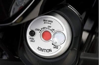
5. Ignition switch

Ignition switch is a device to activate and deactivate the CDI system as a whole. Ignition switches are usually controlled by an ID key, each vehicle has a different key channel.
6. Spark plug
The function of the spark plug is to convert 20,000 V electrical energy into an electric spark. the way the spark plug works is actually quite simple, just by providing a gap between the electrode (+) and ground (-).
Automatically, an electric spark will be formed because the voltage of 20,000 V is very large and is able to jump electrons.
As discussed before (CDI system working principle), the CDI system is very different from conventional ignition systems such as battery ignition or magneto ignition.
Then what are the components of the CDI system? let's discuss.
6 Parts of CDI Ignition system and function
Why only 6? that's because the design of the CDI system is simpler so it doesn't need a lot of parts.
1. Source of energy (altenator or battery)
The first component is the energy provider, there are two types of components that can be used as energy providers in the CDI system, alternator and battery.
The alternator can generate electrical energy when the engine crankshaft rotates, the electric current generated is AC. While the battery, is a component of storing electrical energy. The battery can deliver electrical energy directly without turn the engine crankshaft. The electric current generated is DC.
From the explanation above we can see that there is a striking difference between the alternator and battery, the alternator produces AC current while the battery produces DC current. That is why there are two types of schemes in the CDI system, namely the AC CDI system (using an alternator) and the DC CDI system (using batteries).
Although the types of currents are different, both types have the same process. In an AC CDI system, the AC current will be converted into DC by a diode in the CDI unit.
2. CDI unit
CDI unit is a unit that contains several electronic components to trigger the induction of the ignition coil.
So, in this system CDI unit has the same function as breaker point on conventional ignition system.
What are the components in a CDI unit?
- Diode (AC CDI system)
- Voltage amplifier (DC CDI system)
- Capacitor
- SCR
Diodes are electronic components that have function to convert AC current into DC. As explain in the first point, in the AC CDI system the source of electricity is obtained from the alternator. But the alternator produces AC current.
Therefore, the diode acts as a hardware to convert AC current into DC.
While the voltage amplifier is a special component in the DC CDI system which has function to increase the battery voltage from 12 V to 200 V. This is because the capacitor requires around 200 V voltage for charging while the battery voltage is only 12 V.
But why does the AC CDI system not have a voltage amplifier?
The answer, because the voltage generated by the alternator has reached 200 V so it does not require a voltage amplifier.
Capacitor is an electronic component that can store a voltage at a certain capacity and can release the stored voltage simultaneously. In CDI systems, the discharged voltage of the capacitor is used to induce an ignition coil.
We know before that the capacitor has been charged by the electricity provider (alternator / battery) with a voltage of around 200 V. The voltage will be released simultaneously to cause a very large induction.
While the SCR (silicon controlled rectifier) is a component to determine when the capacitor charged and when the capacitor discharged.
The works of SCR is by open the gate from the power source channel directly to the ground. That will make the current from the power source flow directly to ground so that the capacitor can release voltage.
3. Pick up the coil
The pickup coil is a detector to detect ignition timming. The pickup coil consists of a coil placed near the crankshaft. On the crankshaft there is a protrusion that will hit the pickup coil, this protrusion indicates ignition timing.
When the pickup coil hits the cam, the pickup coil will send pulses or electric waves.
The pulse is sent to the SCR to determine the capacitor. So the pulse from the pick up coil becomes the guidance of the SCR to be active.
4. Ignition coil
The ignition coil on the CDI system works when there is a voltage being applied, this is different from a conventional ignition system that utilizes a drop voltage to induce an ignition coil.
So the ignition coil design is slightly different.
In general the ignition coil on the CDI system is the same as the step up transformer, where the secondary primary has a coil of 100 times more than the primary coil. This causes the secondary voltage to be 100 times greater than the primary voltage, so that when the discharged voltage from capacitor is aplied, then the voltage produced by the ignition coil reaches 20,000 V.
5. Ignition switch
Ignition switch is a device to activate and deactivate the CDI system as a whole. Ignition switches are usually controlled by an ID key, each vehicle has a different key channel.
6. Spark plug
The function of the spark plug is to convert 20,000 V electrical energy into an electric spark. the way the spark plug works is actually quite simple, just by providing a gap between the electrode (+) and ground (-).
Automatically, an electric spark will be formed because the voltage of 20,000 V is very large and is able to jump electrons.


